WA2EBY Amp
The WA2EBY Amp posted April 1999 in QST.
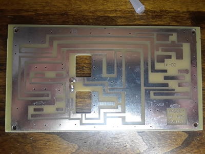
This is one of the more skilled builds I have done. The boards you will see have no parts placement. That said it was still a lot of fun to build. All build info along with stats are at the bottom of the page.
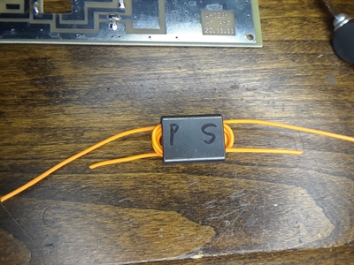
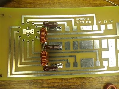
T3 P = Primary S = Secondary
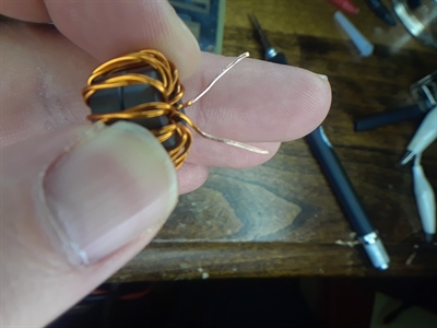
The T2 core was a tough wrap. I would suggest some form of glue to hold them as you wrap.
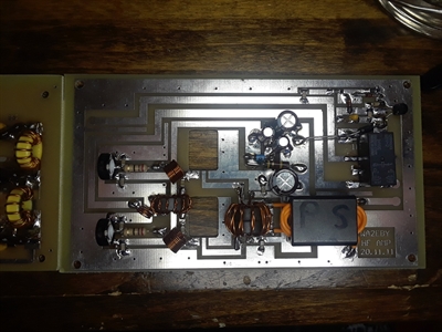
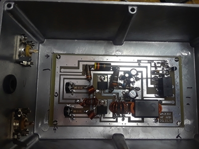
Just before final assembly, note the IRF510's are not installed. I always save the fets for last to help the board line up with heat sink and case. Also note the bias trimmers. This is the suggested part but, depending on how you mount they might be better as the top-down variations. Mine worked but had to use the back side of the trimmer, it was tricky.
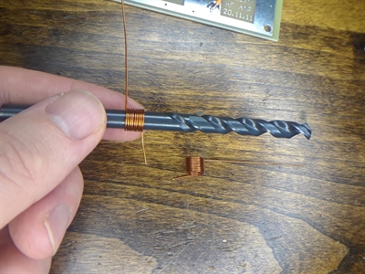
L1 and L2 are done using a 1/4 drill bit. The build notes I followed did not match some of the pictures, just follow the notes all is well.
Parts Parts Parts
The WA2EBY is setup for 1w drive levels, I will be using this with my Bitx40 and soon the Ubitx. That said the pad for higher drive levels is in the QST article.
R8—130 Ω, 1 W; for 7 dB pad
(5 W in, 1 W out)
R9—43 Ω, 2 W; for 7 dB pad
(5 W in, 1 W out)
R10—130 Ω, 3 W; for 7 dB pad
(5 W in, 1 W out)
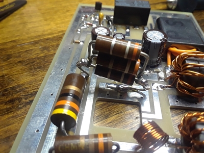
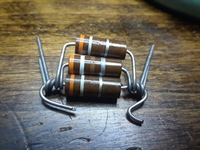
The carbon composite Allen Bradly resistors I used are hard to find and tend to cost a few bucks each in some cases. To me they are well worth it. I did not end up finding anything near 130Ω in a 3W rating so I went with 3x 390Ω 1W instead. It was a tough fit but it works great.
Don't forget to cut the trace under R9 if you add the pad.
The WA2EBY is setup for 1w drive levels, I will be using this with my Bitx40 and soon the Ubitx. That said the pad for higher drive levels is in the QST article.
R8—130 Ω, 1 W; for 7 dB pad
(5 W in, 1 W out)
R9—43 Ω, 2 W; for 7 dB pad
(5 W in, 1 W out)
R10—130 Ω, 3 W; for 7 dB pad
(5 W in, 1 W out)
The carbon composite Allen Bradly resistors I used are hard to find and tend to cost a few bucks each in some cases. To me they are well worth it. I did not end up finding anything near 130Ω in a 3W rating so I went with 3x 390Ω 1W instead. It was a tough fit but it works great.
Don't forget to cut the trace under R9 if you add the pad.
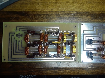
The LPF stage was the easy part, all be it the longest. I suggest good NOS or new Silver Mica Caps. I get all that I can from Kitsandparts.com, who also sells a nice toroid kit for this build. Anything that couldn't be found at Mouser or Kits and parts I turned to Ebay.
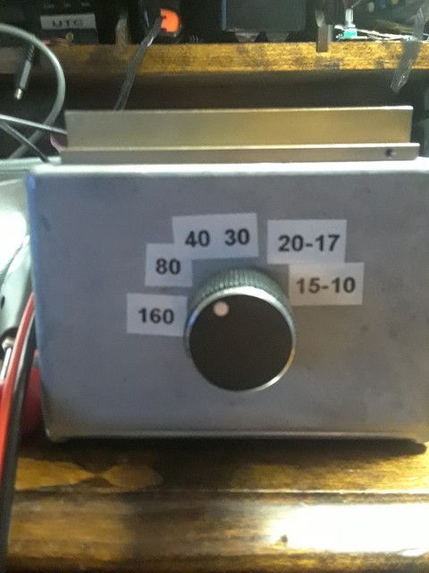
The LPF stages are not in "order", 20/17 is flipped with 15/10. Be sure to follow the build notes. It can not be seen in the photo but I used a fine pencil to mark the bands on the pcb to save from an error.
The LPF stages are not in "order", 20/17 is flipped with 15/10. Be sure to follow the build notes. It can not be seen in the photo but I used a fine pencil to mark the bands on the pcb to save from an error.
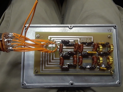
With some spare teflon wire I made quick work of the wire up.
From the pic above you can see my power IN is going over the RF out as well as over the amp (ignore the random coax from the meter across the picture). I didn't end up leaving that alone. The power is now along the bottom side of the panel under the RF out. RF out was also lowered in the case more to avoid any issues with the LPF. The LPF in and out should also be as short as possible.
The End Is Near!
Some notes after daily use.
COR:
Its nice and simple and works but, the switch to RX is just a bit too slow for me. I will either be adding a foot switch or adjusting the COR.
Power out:
I have seen it all over the map with the Bitx, this is more than likely do to the simple fact that the Bitx also uses IRF510's. The 510's work but they are not ideal RF devices.
When frequency on the bitx40 changes so does its max drive. Same goes for the WA2EBY as you can see from the swr and power readings on the left. With the 510 final in the radio and amp, output can be a mixed bag.
Heat is also a large factor with this amp as well. I now use a 12V muffin fan at 5v to keep air moving on the heatsink.
I did the final testing with a Yaesu FT-891 at 5W CW key down.
PCB:
If you get yours from the same place I did some of the build notes do not apply. The 510 hole size, grounding tabs and a grounding error has been fixed in that version.
In testing.
So I ran this on 24v not 28v and here are the stats so far.
5w drive
Total amps CW key down 2.998
swr on all bands
160m = 1.02 almost 50W
80m = 1.04 45W
40m = 1.10 40W
30m = 1.16 36W
20m = 1.27 28W
17m = 1.38 22W
15m = 1.43 20W
10m = 1.44 15W or less
So I ran this on 24v not 28v and here are the stats so far.
5w drive
Total amps CW key down 2.998
swr on all bands
160m = 1.02 almost 50W
80m = 1.04 45W
40m = 1.10 40W
30m = 1.16 36W
20m = 1.27 28W
17m = 1.38 22W
15m = 1.43 20W
10m = 1.44 15W or less
COR Update
So I found the 3 or so second delay for return to RX just to long. After playing with it more I found 1uf at C14 over the stock 2.2uf was just about perfect.